Threat modelling
1. Introduction
This tutorial shows how to get started with threat modeling and data flow diagrams using the Cyberismo secure development essentials module.
The secure development essentials module includes a lot of resources for secure development. If you only need it for threat modelling, you can set it in a mode that hides all the unnecessary details and lets you focus on threat modelling.
The Cyberismo secure development essentials module defines card types and link types for creating dataflow models with processes, external entities, data storages, trust boundaries and data flows. This enables you to model your software systems using cards and links in Cyberismo.
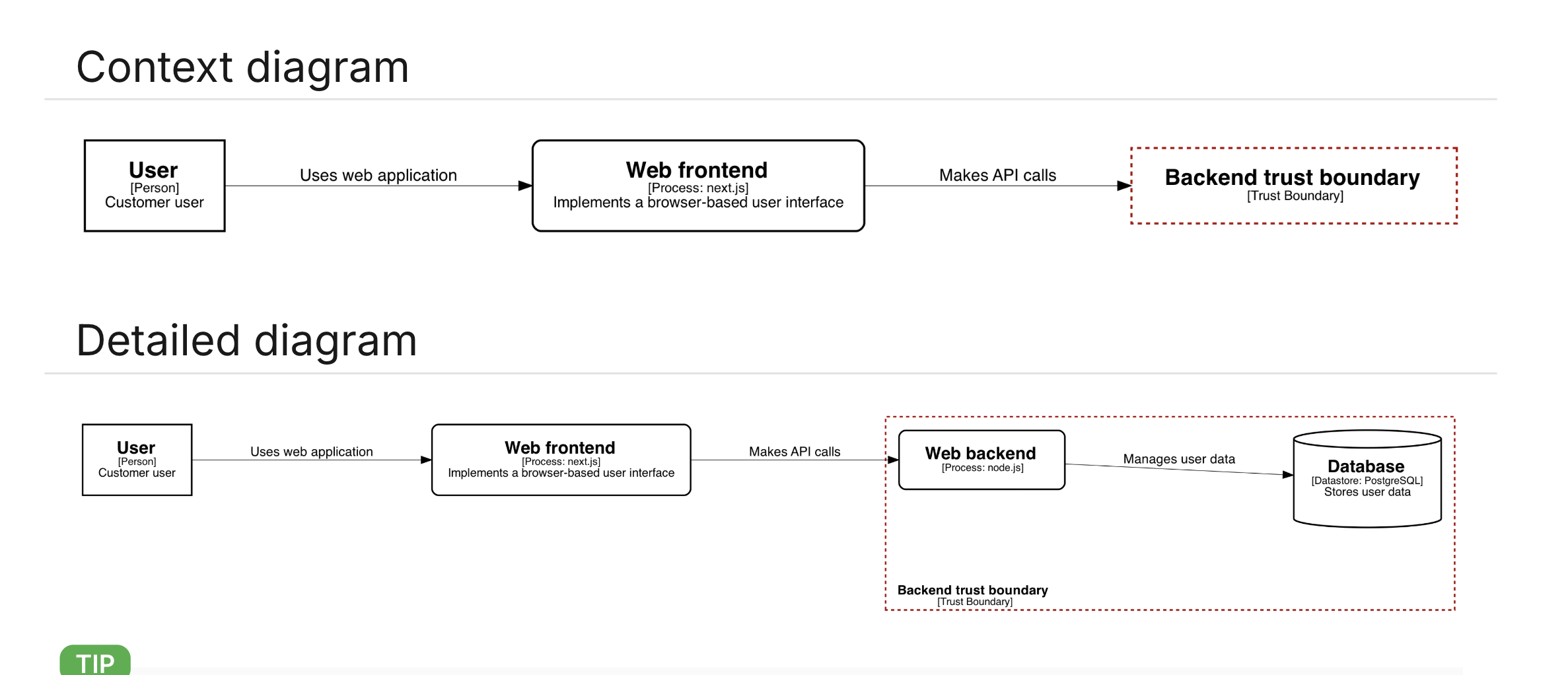
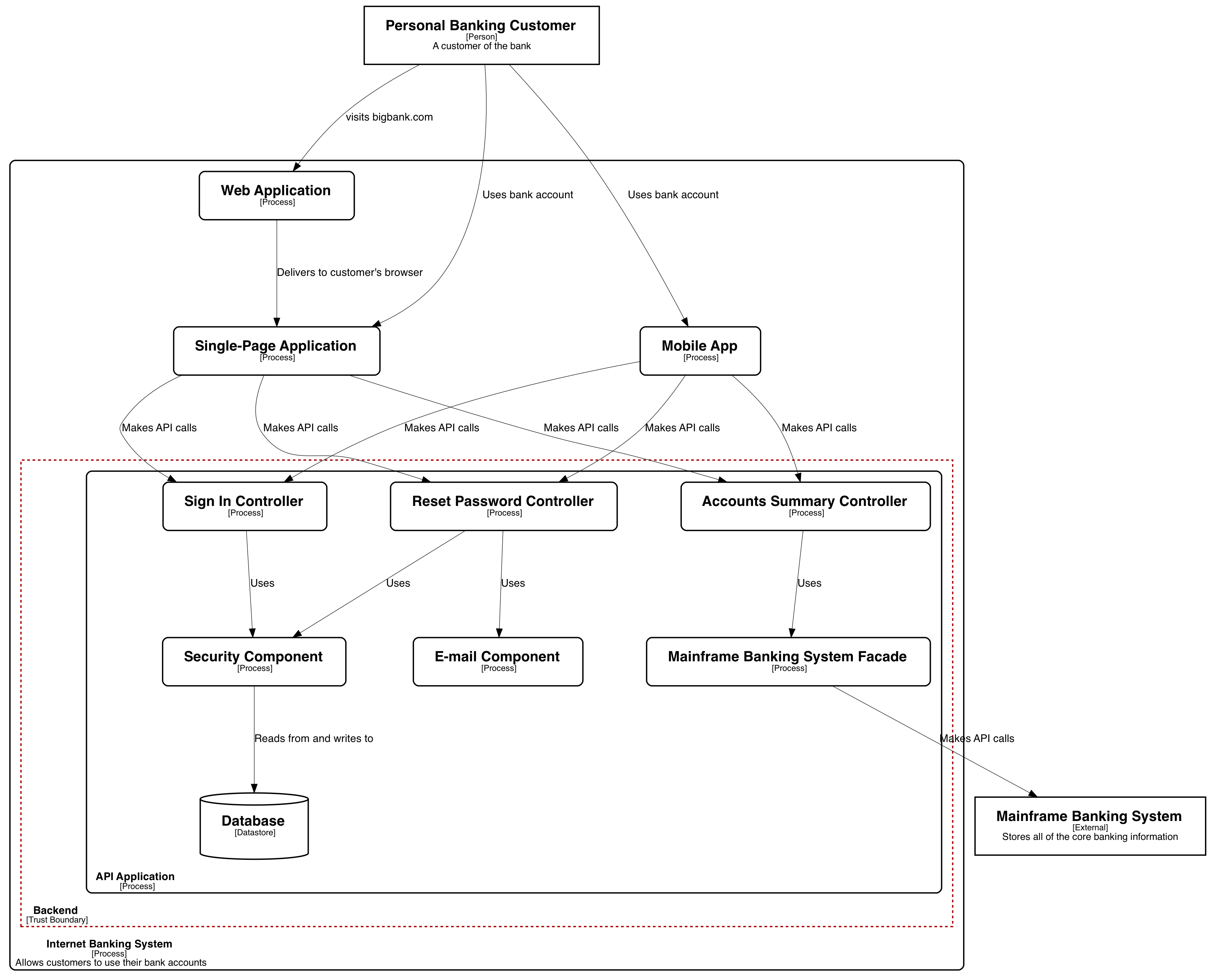
The module uses graph macros that translate the model into graphical views. You can generate different views from the same data. For example, a high-level context diagram for an internet banking system[1] could look like this:

If you draw a diagram that includes all the details of the model, you could get an image like this:
3. Start the Cyberismo app
Change to the the directory of your Cyberismo project and start the Cyberismo app:
$ cyberismo appThen open a browser and navigate to http://localhost:3000/.
4. Set the Target adoption step as None
To configure your project so that you can focus on threat modelling:
-
Navigate to the development project that you created in the previous tutorial.
-
Click Edit and change the Target adoption step metadata field as None.
The Cyberismo app will now hide all content that has been marked for Adoption step 1, step 2, or step 3, so you can focus on threat modeling and on a high-level risk assessment.
5. Create a threat model
To create a threat model:
-
Navigate to Design / Manage threat models
-
Click Create a threat model
6. Add entities and trust boundaries
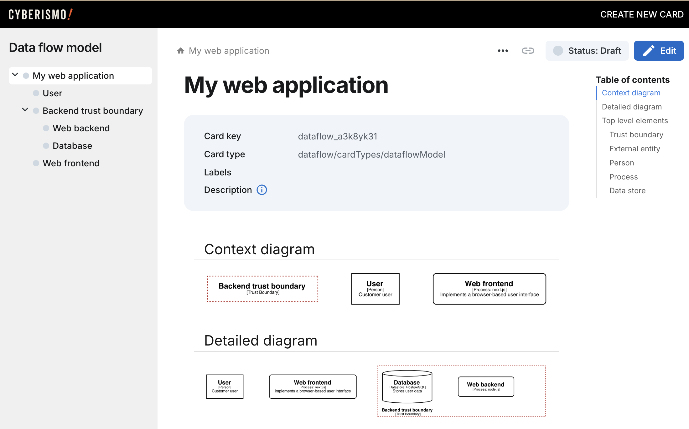
The threat model includes a starting point for a dataflow model, with a User and a Solution trust boundary components.
Here are some steps you can try out:
-
Edit the Solution trust boundary and rename it as Backend trust boundary
-
Create a process called Web front end at the top level
-
Under the trust boundary, create a process Web backend and a datastore called Database.
-
You can enter descriptions and technologies, which will be used in the diagrams.
Each card will show a graph that illustrates the entity, and the top level dataflow model shows a context view and a detailed view:
7. Add data flows
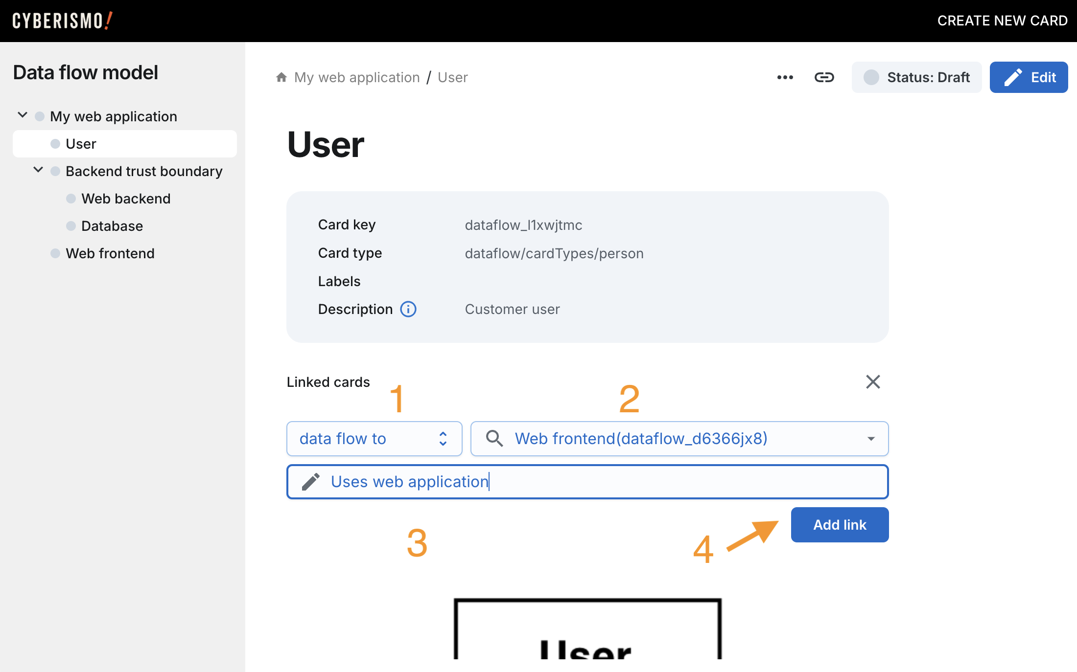
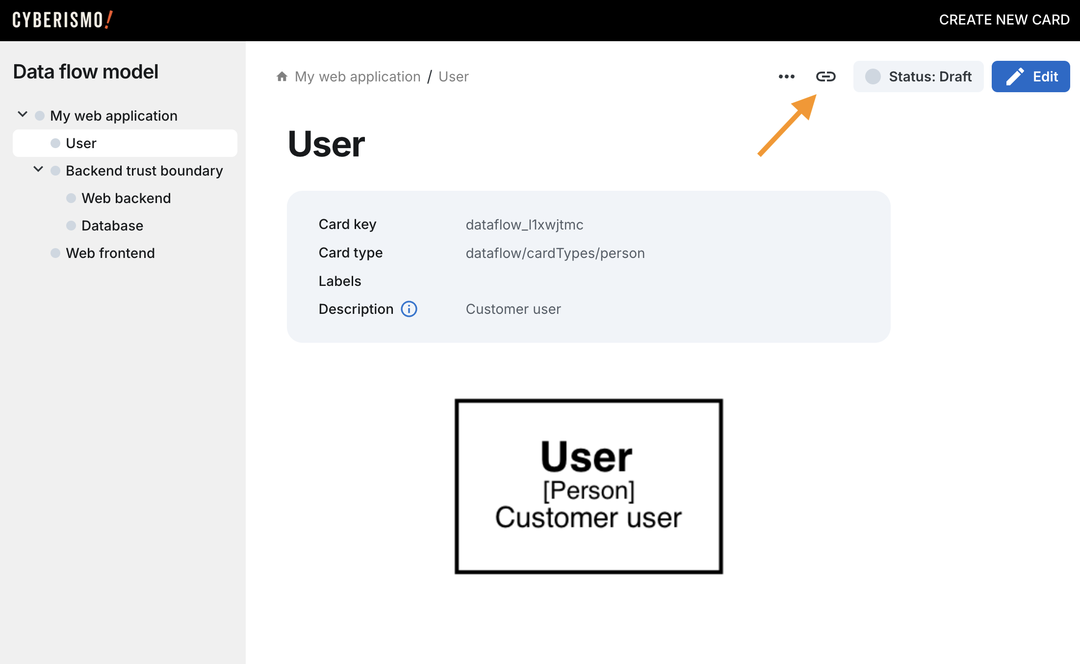
Dataflows are entered as links between cards. To add a link, click the link icon at the top of the view:
Fill in the details of the dataflow:
-
Select dataflow to or dataflow from as the link type
-
Select the other end of the dataflow
-
Write a short description of the dataflow
-
Click Add link